
Energy Conversion
1. A diac is a
A. Unidirectional device
B. Device with three leads
C. Bidirectional device
D. both “unidirectional device” and “device with three leads”
2. The forward breakover voltage of an SCR
A. Decreases as the gate current increases
B. Cannot be controlled by gate current
C. Increases as the gate current increases
D. None of the above
3. Which of the following is best suited for controlling power in ac circuits?
A. the SCR.
B. The triac
C. An ordinary rectifier diode
D. None of the above
4. For a UJT, the intrinsic standoff ratio, ƞ, equals
A. RB1/RB2
B. RB1/(RB1+RB2)
C. RB2/(RB1+RB2)
D. None of the above
5. Once an SCR is conducting,
A. Its anode to cathode voltage increases substantially
B. The only way to turn it off is with a positive gate voltage
C. It can never be turned off
D. The gate loses all control
6. For an SCR, the holding current, IH, is defined as the
A. Minimum anode current required to hold the SCR in its conducting state
B. Maximum anode current that the SCR can safely handle
C. Minimum amount of anode current that will keep the SCR off
D. None of the above
7. An RC phase-shifting network is used in SCR and triac circuits to
A. Control the conduction angle of the thyristor
B. Handle some of the load current
C. Vary the holding current
D. None of the above
8. Which is the most sensitive mode of operation for a triac?
A. mode 1
B. mode 2
C. mode 3
D. mode 4
9. Thyristors are used extensively in
A. Small signal amplifiers
B. Stereo amplifiers
C. high-power switching applications
D. None of the choices
10. A triac is equivalent to
A. Two diacs in parallel
B. an SCR without a gate lead
C. Two ordinary diodes in parallel
D. two SCRs in parallel
11. A thyristor (SCR) is a
A. P-N-P device
B. N-P-N device
C. P-N-P-N device
D. P-N device
12. Which terminal does not belong to the SCR?
A. Anode
B. Gate
C. Base
D. Cathode
13. An SCR is a
A. Four layer, four junction device
B. Four layer, three junction device
C. Four layer, two junction device
D. Three layer, single junction device
14. Choose the false statement.
A. SCR is a bidirectional device
B. SCR is a controlled device
C. In SCR the gate is the controlling terminal
D. SCR are used for high-power applications
15. In the SCR structure the gate terminal is located
A. Near the anode terminal
B. Near the cathode terminal
C. In between the anode & cathode terminal
D. None of the mentioned
16. The static V-I curve for the SCR is plotted for
A. Ia (anode current) vs Ig (gate current), Va(anode – cathode voltage) as a parameter
B. Ia vs Va with Ig as a parameter
C. Va vs Ig with Ia as a parameter
D. Ig vs Vg with Ia as a parameter
17. If the cathode of an SCR is made positive with respect to the anode & no gate current is applied then
A. All the junctions are reversed biased
B. All the junctions are forward biased
C. Only the middle junction is forward biased
D. Only the middle junction is reversed biased
18. For an SCR in the reverse blocking mode, (practically)
A. Leakage current does not flow
B. Leakage current flows from anode to cathode
C. Leakage current flows from cathode to anode
D. Leakage current flows from gate to anode
19. With the anode positive with respect to the cathode & the gate circuit open, the SCR is said to be in the
A. Reverse blocking mode
B. Reverse conduction mode
C. Forward blocking mode
D. Forward conduction mode
20. For an SCR in the forward blocking mode (practically)
A. Leakage current does not flow
B. Leakage current flows from anode to cathode
C. Leakage current flows from cathode to anode
D. Leakage current flows from gate to anode
21. The forward break over voltage is the
A. anode-cathode voltage at which conduction starts with gate signal applied
B. anode-cathode voltage at which conduction starts with no gate signal applied
C. Gate voltage at which conduction starts with no anode-cathode voltage
D. Gate voltage at which conduction starts with anode-cathode voltage applied
22. For a forward conducting SCR device, as the forward anode to cathode voltage is increased
A. The device turns on at higher values of gate current
B. The device turns on at lower values of gate current
C. The forward impedance of the device goes on increasing
D. The forward impedance of the device goes on decreasing
23. A thyristor can be brought from the forward conduction mode to forward blocking mode by
A. The dv/dt triggering method
B. Applying a negative gate signal
C. Applying a positive gate signal
D. Applying a reverse voltage across anode-cathode terminals
24. Usually, the forward voltage triggering method is not used to turn-on the SCR because
A. It increases losses
B. It causes noise production
C. It may damage the junction & destroy the device
D. Relatively it’s an inefficient method
25. Among the following, the most suitable method to turn on the SCR device is the
A. Gate triggering method
B. dv/dt triggering method
C. Forward voltage triggering method
D. Temperature triggering method
26. The forward break over voltage is maximum when
A. Gate current = ∞
B. Gate current = 0
C. Gate current = -∞
D. It is independent of gate current
27. For the SCR to remain in the ON (conducting) state
A. Gate signal is continuously required
B. No continuous gate signal is required
C. No forward anode-cathode voltage is required
D. Negative gate signal is continuously required
28. The value of anode current required to maintain the conduction of an SCR even though the gate signal is removed is called as the
A. Holding current
B. Latching current
C. Switching current
D. Peak anode current
29. In the reverse blocking mode the middle junction (J2) has the characteristics of that of a
A. transistor
B. capacitor
C. inductor
D. None of the mentioned
30. ________ are semiconductor thyristor devices which can be turned-on by light of appropriate wavelengths.
A. LGTOs
B. LASERs
C. MASERs
D. LASCRs
31. A thyristor can be used as
A. A resistor
B. An amplifier
C. A switch
D. A power source
32. Positive feedback means the returning signal
A. Opposes the original change
B. Aids the original change
C. Is equivalent to negative feedback
D. Is amplified
33. A latch always uses
A. Transistors
B. Feedback
C. Current
D. Positive feedback
34. To turn on a four-layer diode, you need
A. A positive trigger
B. low-current drop out
C. Breakover
D. Reverse-bias triggering
35. The minimum input current that can turn on a thyristor is called the
A. Holding current
B. Trigger current
C. Breakover current
D. Low-current drop out
36. The only way to stop a four-layer diode that is conducting is by
A. A positive trigger
B. Low-current drop out
C. Breakover
D. Reverse-bias triggering
37. The minimum anode current that keeps a thyristor turned on is called the
A. Holding current
B. Trigger current
C. Breakover current
D. Low-current drop out
38. A silicon controlled rectifier has
A. Two external leads
B. Three external leads
C. Four external leads
D. Three doped regions
39. A SCR is usually turned on by
A. Breakover
B. A gate trigger
C. Breakdown
D. Holding current
40. SCRs are
A. Low-power devices
B. Four-layer diodes
C. High-current devices
D. Bidirectional
41. The usual way to protect a load from excessive supply voltage is with a
A. Crowbar
B. Zener diode
C. Four-layer diode
D. Thyristor
42. An RC snubber protects an SCR against
A. Supply over voltages
B. False triggering
C. Breakover
D. Crowbarring
43. When a crowbar is used with a power supply, the supply needs to have a fuse or
A. Adequate trigger current
B. Holding current
C. Filtering
D. Current limiting
44. The photo-SCR responds to
A. Current
B. Voltage
C. Humidity
D. Light
45. The diac is a
A. Transistor
B. Unidirectional device
C. Three-layer device
D. Bidirectional device
46. The triac is equivalent to
A. A four-layer diode
B. Two diacs in parallel
C. A thyristor with a gate lead
D. Two SCRs in parallel
47. The unijunction transistor acts as a
A. Four-layer diode
B. Diac
C. Triac
D. Latch
48. Any thyristor can be turned on with
A. Breakover
B. Forward-bias triggering
C. Low-current dropout
D. Reverse-bias triggering
49. A Shockley diode is the same as a
A. four-layer diode
B. SCR
C. diac
D. triac
50. The trigger voltage of an SCR is closest to
A. 0 V
B. 0.7 V
C. 4 V
D. Breakover voltage
51. Any thyristor can be turned off with
A. Breakover
B. Forward-bias triggering
C. Low-current drop out
D. Reverse-bias triggering
52. Exceeding the critical rate of rise produces
A. Excessive power dissipation
B. False triggering
C. Low-current drop out
D. Reverse-bias triggering
53. A four-layer diode is sometimes called a
A. Unijunction transistor
B. Diac
C. PNPN diode
D. Switch
54. A latch is based on
A. Negative feedback
B. Positive feedback
C. The four-layer diode
D. SCR action
55. _________ device from the thyristor family has its gate terminal connected to the n-type material near the anode.
A. SCR
B. RCT
C. PUT
D. SUT
56. The Programmable Unijunction Transistor (PUT) turns on & starts conducting when the
A. Gate voltage exceeds anode voltage by a certain value
B. Anode voltage exceeds gate voltage by a certain value
C. Gate voltage equals the anode voltage
D. Gate is given negative pulse w.r.t to cathode
57. The equivalent circuit of SUS (Silicon Unilateral Switch) consists of
A. A diode in series with a PUT
B. A diode in parallel with a PUT
C. A diode in anti-parallel with a PUT
D. Two diodes
58. From the following list of devices, choose the device that only turns-on for a fixed-value of anode-cathode voltage
A. PUT
B. SCR
C. SUS
D. BJT
59. The SCS (Silicon Controlled Switch) is a
A. Two terminal device
B. Three terminal device
C. Four terminal device
D. Five terminal device
60. The SCS is a four layer, four terminal thyristor. Can be turned on by
A. The anode gate
B. The cathode gate
C. Either of the gates
D. Gating both the gates together
61. The SCS (Silicon Controlled Switch) can be turned on by two methods, by applying __________ and __________
A. Positive pulse to the anode gate, positive pulse to the cathode gate
B. Positive pulse to the anode gate, negative pulse to the cathode gate
C. Negative pulse to the anode gate, positive pulse to the cathode gate
D. Negative pulse to the anode gate, negative pulse to the cathode gate
62. Which of the following devices provide complete isolation between triggering circuit and power circuit?
A. PUT
B. LASCR
C. SUS
D. DIAC
63. The DIAC can be represented by
A. two SCRs in anti-parallel
B. two SCRs in parallel
C. Two diodes in anti-parallel
D. Two diodes in parallel
64. The TRIAC can be represented by
A. two SCRs in anti-parallel
B. two SCRs in parallel
C. Two diodes in anti-parallel
D. Two diodes in parallel
65. The TRIAC’s terminals are
A. gate, anode, cathode
B. MT1, MT2, gate
C. gate1, gate2, anode, cathode
D. MT1, MT2, gate1, gate2
66. In the ___________ type of chopper, two stage conversions takes place.
A. AC-DC
B. AC link
C. DC link
D. None of the mentioned
67. Choppers converter
A. AC to DC
B. DC to AC
C. DC to DC
D. AC to AC
68. A chopper may be thought as a
A. Inverter with DC input
B. DC equivalent of an AC transformer
C. Diode rectifier
D. DC equivalent of an induction motor
69. Which device can be used in a chopper circuit?
A. BJT
B. MOSFET
C. GTO
D. All of the mentioned
70. A chopper is a
A. Time ratio controller
B. AC to DC converter
C. DC transformer
D. High speed semiconductor switch
71. What is the duty cycle of a chopper ?
A. Ton/Toff
B. Ton/T
C. T/Ton
D. Toff x Ton
72. The load voltage of a chopper can be controlled by varying the
A. Duty cycle
B. Firing angle
C. Reactor position
D. Extinction angle
73. The values of duty cycle (α) lies between
A. 0<α<1
B. 0>α>-1
C. 0<=α<=1
D. 1<α<100
74. If T is the time period for a chopper circuit and α is its duty cycle, then the chopping frequency is
A. Ton/α
B. Toff/α
C. α/Toff
D. α/Ton
75. Find the output voltage expression for a step down chopper with Vs as the input voltage and α as the duty cycle.
A. Vo = Vs/α
B. Vo = Vs x α
C. Vo = Vs2/α
D. Vo = 2Vs/απ
76. If a step up chopper’s switch is always kept off then (ideally).
A. Vo = 0
B. Vo = ∞
C. Vo = Vs
D. Vo > Vs
77. If a step up chopper’s switch is always kept open then (ideally)
A. Vo = 0
B. Vo = ∞
C. Vo = Vs
D. Vo > Vs
78. Find the average value of output current of a basic step-down chopper, with duty cycle = α and load = R Ω.
A. I = Vs x α
B. I = (Vs x α)/R
C. I = 0
D. I = Vs/R
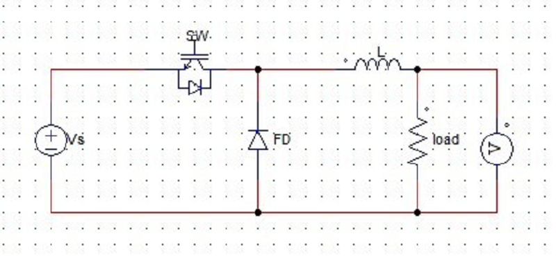
79. For the below given circuit, find the output current at the instant of commutation.
A. Vo/R
B. Vs/R
C. 0
D. α/2
80. For a step-down chopper, find the rms value of output voltage. Let α be the duty cycle and Vs be the input voltage.
A. α x Vs
B. Vs/α
C. √α x Vs
D. Vs/2
81. A step down chopper is operated at 240V at duty cycle of 75%. Find the value of RMS switch (IGBT/MOSFET) current. Take R = 10 Ω.
A. 2.07 A
B. 200 mA
C. 1.58 A
D. 2.4 A
82. Find the expression for effective input resistance of a step down chopper. With R load and duty cycle = α.
A. R x α
B. R/2
C. 0
D. R/α
83. A step-up chopper has input voltage of 220 V and output voltage of 660 V. If the conducting time of the IGBT based chopper is 100 μs, compute Toff width of the output voltage pulse.
A. 100 μs
B. 150 μs
C. 50 μs
D. Insufficient data
84. For a step-up chopper, when the duty cycle is increased the average value of the output voltage
A. increases
B. decreases
C. Remains the same
D. None of the mentioned
85. For a step-down chopper, when the duty cycle is increased the average value of the output voltage
A. increases
B. decreases
C. Remains the same
D. None of the mentioned

86. What is the voltage across the R load when only T2 is conducting?
A. Vs
B. Vs/2
C. 2Vs
D. Zero
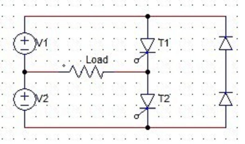
87. T1 is fired at 0,T and so on and T2 at T/2, 3T/2 etc. What is the frequency of the alternating voltage obtained?
A. 50 Hz
B. T Hz
C. 1/T Hz
D. T/2 Hz

88. Vs/2 = 50 V. Find, the rms AC voltage that would be ideally obtained.
A. 50 V
B. 100
C. 0.707 x 50 V
D. 0.707 x 100 V
89. The voltage in a single phase half wave inverter varies between
A. Vs and 0 C.
B. Vs/2 and 0
C. Vs/2 and –Vs/2
D. Vs and –Vs
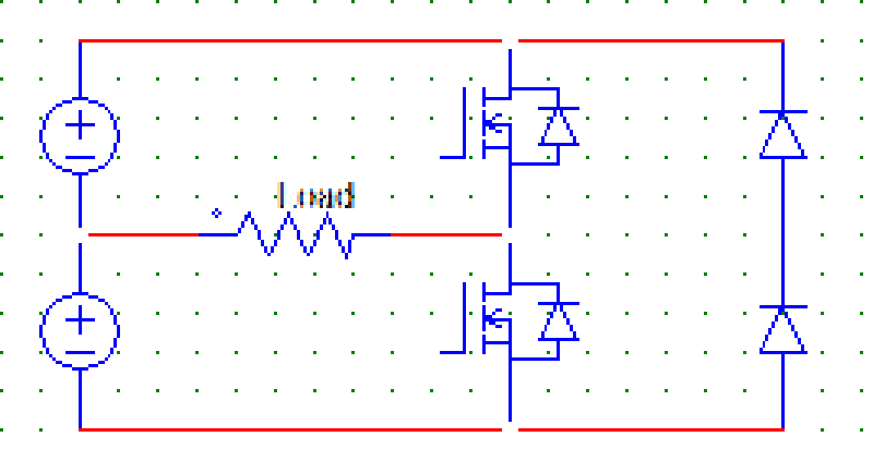
90. Below given is a
A. SCR based inverter
B. MOSFET based inverter
C. IGBT based inverter
D. None of the mentioned
91. The output of a single-phase half bridge inverter on R load is ideally
A. A sine wave
B. A square wave
C. A triangular wave
D. Constant dc
92. Find the conduction time of the diodes if the SCRs are fired at 0 and T/2 respectively in a single phase half wave inverter with R load.
A. 0
B. T/2
C. 2/T
D. Insufficient data
93. The output current wave of a single-phase full bridge inverter on RL load is
A. A sine wave
B. A square wave
C. A triangular wave
D. Constant dc
94. Single-phase full bridge inverters requires
A. 4 SCRs and 2 diodes
B. 4 SCRs and 4 diodes
C. 2 SCRs and 4 diodes
D. 2 SCRs and 2 diodes
95. Identify the circuit given below.
A. Full wave series inverter
B. Half wave series inverter
C. Full wave bridge inverter
D. Full wave parallel inverter
Use this statement to answer the next 5 questions. A thyristor half-wave controlled converter has a supply voltage of 220V at 60Hz, α=40 deg, and a load resistance of 200 Ω.
96. Find VL(ave).
A. 108.8 V
B. 100.8
C. 71.28 V
D. 87.45 V
97. Find IL(ave).
A. 1.08 A
B. 1.01 A
C. 0.437 A
D. 0.782 A
98. Find the IL(rms).
A. 1.67 A
B. 0.75 A
C. 3.11 A
D. 0.77 A
99. Find the PL.
A. 113 W
B. 267 W
C. 344 W
D. 280 W
100. Find the power factor.
A. 0.452
B. 0.244
C. 0.465
D. 0.682
{"name":"Energy Conversion", "url":"https://www.quiz-maker.com/QPREVIEW","txt":"1. A diac is a, 2. The forward breakover voltage of an SCR, 3. Which of the following is best suited for controlling power in ac circuits?","img":"https://www.quiz-maker.com/3012/CDN/98-4815176/123123.jpg?sz=1200"}